Physics 12th Capacitance
Capacitance
1. Introduction
- A capacitor (formerly known as condenser) is a device that can store electronic charge and energy.
- All capacitors consists of a combination of two conductors separated by an insulator.
- The insulator is called dielectric which could be oil, air or paper and many more such materials are there wich can act as a dielectric medium between conducting plates of a capacitor.
- Figure 1 below shows the symbol used to represent a capacitor.
- Now plates of the capacitor are connected to the terminals of a battery, shown below in figure 2, in order to charge it's conducting plates.
- As soon as capacitor is connected to the battery , charge is transferred from one conductor to another.
- Plate connected to positive terminal of the battery becomes positively charged with charge +Q in it and plate connected to negative terminal of the battery becomes negatively charged with cahrge -Q on it i.e. both plates have equal amount of opposite charge .
- Once the capacitor is fully charged potential difference between the conductors due to their equal and opposite charges becomes equal to the potential difference between the battery terminals.
- For a given capacitor Q∝V and the ratio Q/V is constant for a capacitor.
Thus,
Q=CV (1)
where the proportionality constant C is called the capacitance of the capacitor.
- Capacitance of any capacitor depends on shape , size and geometrical arrangement of the conductors.
- When Q is in coulumbs (C) and V is in volts(V) then the S.I. unit of capacitance is in farads(F) where
1F=1 coulumb/volt
- One farad is the capacitance of very large capacitor and it's submultiples such as microfarad(1μF=10-6) or picofarad(1pF=10-12) are generally used for practical applications.
2. Calculation of capacitance
- For calculating capacitance of a capacitor first we need to find the potential difference between it's two conducting plates having charge +Q and -Q.
- For simple arrangements of conductors like two equivalent parallel plates kept at distance d apart or two concentric conducting spheres etc., potential difference can be found first by calculating electric field from gauss's law or by Coulumb's law.
- After calculating electric field , potential difference can be found by integrating ellectric field using the relation
Va-Vb=∫E.dr
where the limits of integration goes from a to b.
- Once we know the potential difference between two conductors of the capacitor , it's capacitance can be calculated from the relation
C=Q/V (2)
- Calculation of capacitance of some simple arrangements would be illustrated in following few articles.
3. Parallel plate capacitor
- A parallel plate capacitor consists of two large plane parallel conducting plates separated by a small distance shown below in the figure 3.
- Suppose two plates of the capacitor has equal and opposite charge Q on them. If A is the area of each plate then surface charge density on each plate is
σ=Q/A
- We have already calculated field between two oppositely charged plates using gauss's law which is
E=σ/ε0=Q/ε0A
and in this result effects near the edges of the plates have been neglected.
- Since electric field between the plates is uniform the potential difference between the plates is
V=Ed=Qd/ε0A
where , d is the separation between the plates.
- Thus, capacitance of parallel plate capacitor in vacuum is
C=Q/V=ε0A/d (3)
- From equation 3 we see that quantities on which capacitance of parallel plate capacitor depends i.e.,ε0 , A and d are all constants for a capacitor.
- Thus we see that in this case capacitance is independent of charge on the capacitor but depends on area of it's plates and separation distance between the plates.
4.Cylinderical capacitor
- A cylinderical capacitor is made up of a conducting cylinder or wire of radius a surrounded by another concentric cylinderical shel of radius b (b>a).
- Let L be the length of both the cylinders and charge on inner cylender is +Q and charge on outer cylinder is -Q.
- For calculate electric field between the conductors using Gauss's law consider a gaussian consider a gaussian surface of radius r and length L1 as shown in figure 4.
- According to Gauss's law flux through this surface is q/ε0 where q is net charge inside this surface.
- We know that electric flux is given by
φ=E.A
=EAcosθ
=EA
since electric field is constant in magnitude on the gaussian surface and is perpandicular to this surface. Thus,
φ=E(2πrL)
since φ=q/ε0
=> E(2πrL)=(λL)/ε0
where λ = Q/L = charge per unit length
=>
or,
(4)
- If potential at inner cylinder is Va and Vb is potential of outer cylinder then potential difference between both the cylinders is
V=Va and Vb=∫Edr
where limits of integration goes from a to b.
- Potential of inner conductor is greater then that of outer conductor because inner cylinder carries positive charge. Thus potential difference is
- Thus capacitance of cylinderical capacitor is
C=Q/V
or,
| C = | 2πε0L Qln(b/a) |
| ln(b/a) |
(5)
- From equation 5 it can easily be concluded that capacitance of a cylinderical capacitor depends on length of cylinders.
- More is the length of cylinders , more charge could be stored on the capacitor for a given potential difference.
5. Spherical capacitor
- A spherical capacitor consists of a solid or hollow spherical conductor of radius a , surrounded by another hollow concentric spherical of radius b shown below in figure 5
- Let +Q be the charge given to the inner sphere and -Q be the charge given to the outer sphere.
- The field at any point between conductors is same as that of point charge Q at the origin and charge on outer shell does not contribute to the field inside it.
- Thus electric field between conductors is
- Potential difference between two conductors is
V=Va-Vb
=-∫E.dr
where limits of integration goes from a to b.
On integrating we get potential difference between to conductors as
- Now , capacitance of spherical conductor is
C=Q/V
or,
(6)
- again if radius of outer conductor aproaches to infinity then from equation 6 we have
C=4πε0a (7)
- Equation 7 gives the capacitance of single isolated sphere of radius a.
- Thus capacitance of isolated spherical conductor is proportional to its radius.
6. Capacitors in series and parallel combinations
For prectical applications , two or more capacitors are often used in combination and their total capacitance C must be known.To find total capacitance of the arrangement of capacitor we would use equation
Q=CV
(i) Parallel combination of capacitors
- Figure below shows two capacitors connected in parallel between two points A and B
- Right hand side plate of capacitors would be at same common potential VA. Similarly left hand side plates of capacitors would also be at same common potential VB.
- Thus in this case potential difference VAB=VA-VB would be same for both the capacitors, and charges Q1 and Q2 on both the capacitors are not necessarily equal. So,
Q1=C1V and Q2=C2V
- Thus charge stored is divided amongst both the capacitors in direct proportion to their capacitance.
- Total charge on both the capacitors is,
Q=Q1+Q2
=V(C1+C2)
and
Q/V=C1+C2 (8)
So system is equivalent to a single capacitor of capacitance
C=Q/V
where,
- When capacitors are connected in parallel their resultant capacitance C is the sum of their individual capacitances.
- The value of equivalent capacitance of system is greater then the greatest individual one.
- If there are number of capacitors connected in parallel then their equivalent capacitance would be
C=C1+C2+ C3........... (10)
(ii) Series combination of capacitors
- Figure 7 below shows two capacitors connected in series combination between points A and B.
- Both the points A and B are maintained at constant potential difference VAB.
- In series combination of capacitors right hand plate of first capacitor is connected to left hand plate of next capacitor and combination may be extended foe any number of capacitors.
- In series combination of capacitors all the capacitors would have same charge.
- Now potential difference across individual capacitors are given by
VAR=Q/C1
and,
VRB=Q/C2
- Sum of VAR and VRB would be equal to applied potential difference V so,
V=VAB=VAR+VRB
=Q(1/C1 + 1/C2)
or,
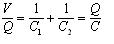
where

i.e., resultant capacitance of series combination C=Q/V, is the ratio of charge to total potential difference across the two capacitors connected in series.
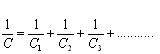
- So, from equation 12 we say that to find resultant capacitance of capacitors connected in series, we need to add reciprocals of their individual capacitances and C is always less then the smallest individual capacitance.
- Result in equation 12 can be summarized for any number of capacitors i.e.,
7. Energy stored in a capacitor
- Consider a capacitor of capacitance C, completely uncharged in the begning.
- Charhing process of capacitor requires expanditure of energy because while charging a capacitor charge is transferred from plate at lower potential to plate at higher potential.
- Now if we start charging capacitor by transporting a charge dQ from negative plate ti the positive plate then work is done against the potential difference across the plate.
- If q is the amount of charge on the capacitor at any stage of charging process and φ is the potential difference across the plates of capacitor then magnitude of potential difference is φ=q/C.
- Now work dW required to transfer dq is
dW=φdq=qdq/C
- To charge the capacitor starting from the uncharged state to some final charge Q work required is
Integrating from 0 to Q
W=(1/C)∫qdq
=(Q2)/2C (14a)
=(CV2)/2
=QV/2
Which is the energy stored in the capacitor and can also be written as
U=(CV2)/2 ---(15)
- From equation 14c,we see that the total work done is equal to the average potential V/2 during the charging process ,multiplied by the total charge transferred
- If C is measured in Farads ,Q in coulumbs and V in volts the energy stored would in Joules
- A parallel plate capacitor of area A and seperation d has capacitance
C=ε0A/d
- electric field in the space between the plates is
E=V/d or V=Ed
Putting above values of V and C in equation 14b we find
W=U=(1/2)(ε0A/d)(Ed)2
=(1/2)ε0E2(Ad)
=(1/2)ε0E2.V ---(16)
- If u denotes the energy per unit volume or energy density then
u=(1/2)ε0E2 x volume
- The result for above equation is generally valid even for electrostatic field that is not constant in space.
8. Effect of Dielectric
- Dielectric are non conducting materials for ex- Glass,mica,wood etc.
- What happened when space between the two plates of the capacitor is filled by a dielectric was first discovered by faraday.
- Faraday discovered that if the space between conductors of the capacitor is occupied by the dielectric,the capacitance of capacitor is increased.
- If the dielectric completely fills the space between the conductors of the capacitor ,the capacitance is increased by an factor K which is characterstics of the dielectric and This factor is known as the dielectric constan.
- Dielectric constant of vaccum is unity.
- Consider a capacitor of capacitance C0 is being charged by the connecting it to a battery.
- If Q0 is the amount of charged on the capacitor at the end of the charging and V0 is potental diffrence across the plates of the capacitor then
C0=Q0 /V0 ----(17)
Thus charge being placed on the capacitor is
Q0=C0V0
- If the battery is diconnected and space between the capacitor is filled by a dielectric the P.D decrease to a new value
V=V0/K.
- Since the original charge is still on the capacitor,the new capacitance will be
C=Q0/V=KQ0/V0=KC0----(19)
- From equation 19 it follows that C is greater then C0.
- Again if the dielectric is inserted while the battery is still connected then battery would have to supply some amount of charge to maintain the P.D between the plates and then total charge on the plates would be Q=KQ0.
- In either of the cases ,capacitance of the capacitor is increase by the amount K.
- For a parallel plate capacitor with dielectric of dielectric constant K between its plates its capacitance becomes
C=εA/D ----(20)
where ε=Kε0
- When a sufficiently strong electric field is applied to any dielectric material it becomes a conductor and this phenomenon is known as dielectric breakdown.
- The maximun electric field a material can withstand without the occurence of breakdown is called dielectric strength of that material.
- Thus field across the capacitor should never exceed breakdown limits in order to store charge on capacitor without leaking.

No comments:
Post a Comment