
Huyghen's principle and interference of light
1. Introduction
- Light is a form of energy .This fact was predicted by Maxwell on theoretical grounds and was verified by Lebedew experimentally in 1901
- Since light is a form of energy, its transmission from one place to another can be understood in terms of transmission of energy
- There are only two modes of propagation of energy through any material medium
- energy is carried by stream of material particles travelling with finite velocity
- Transfer of energy by wave motion without actual travelling with matter
- First mode of energy transfer leads to Newton’s corpuscular theory of light in which he tried to understand travel of light in the straight line assuming that luminous body emits very minute and weightless particles called corpuscles travelling through empty space in straight lines in all directions with the speed of light and carry KE with them
- This corpuscular theory of light can fairly explain the phenomenon of reflection .refraction and rectilinear propagation of light but failed to explain the phenomenon of interference, diffraction and polarization etc
- Second mode of energy transfer leads the wave theory of light which was put forward by Dutch physicist Christian Huygens in 1678
- Huygens suggested that light may be a wave phenomenon produced by mechanical vibrations of an all pervading hypothetical homogenous medium called eather just like those in solids and liguid .This medium was supposed to be mass less with extremely high elasticity and very low density
- At first wave theory of light was not accepted primarily because of Newton’s authority and also light could travel through vacuum and waves require a medium to propagate from one point to other
- Wave theory of light first begin to gain acceptance when double slit experiment of Thomas Young in 1801 established that light is indeed a wave phenomenon
- After Young's double slit interference experiment ,many experiments were carried out by scientists involving interference and diffraction of light waves which could only be satisfactory explained by assuming wave model of light
- Later on in nineteenth century Maxwell put forwards his electromagnetic theory and predicted the existence of electromagnetic waves and calculated the speed of EM waves in free space and found that this value was very close to the measured value of speed of light
- He then suggested light must be an EM wave associated with changing electric and magnetic field which result in the propagation of light or EM waves in vacuum .So no material medium ( like ether suggested by Huygens) is required for the propagation of light wave from one place to another .This argument established that light is a wave phenomenon
- In this chapter we will study the various phenomenon related to wave nature of light
- Consider the figure given below in which a point source of light S starts a distance or wave in air
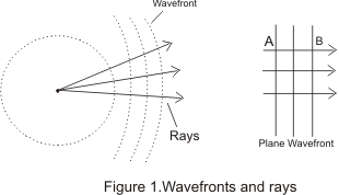
- These waves will travel in all directions with the same velocity c, which is the velocity of light
- After time t, distance travelled by the wave would be equal to ct and light energy thus reaches the surface of the sphere of radius ct with S as its center as shown in figure 1
- The surface of such a sphere is known as wave front of light at this instant and all the particles forming wave front are in the same phase of vibration
- With the passage of time wave travels farther and new wave fronts are obtained .These are all the surfaces of spheres of center S
- Thus at any instant of time wave front may be defined as the locus of all the particles in the medium which are being distributed at the same instant of time and are in the same phase of vibration
- At points very far away from source S such as A or B the wave fronts are parts of the sphere of very large radius so at any such large distances from source wave fronts are substantially plane
- Rays are defined as normal’s to the wave fronts and in case of plane wave fronts ,rays are all parallel to one another as shown in figure 1.
- Huygens principle of wave propagation is a geometrical description used to determine the new position of a wave front at later time from its given position at any given instant of time. It is based on two principles
- Each point on a given or primary wave front acts like a new source sending out disturbance in all directions and are known as secondary wavelets
- The envelope or the tangential plane to these secondary wavelets consitutes the new wave front
- To understand the propagation of wave on the basis of these postulates consider the figure given below
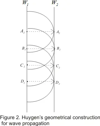
- For simplicity we are considering the simple case of a plane wave
a) Let at time t=0,W1 be the wave front which spates those part of the medium which are undisturbed from those where wave has already reached
b) Each point on W1 acts as a source of secondary waves by sending out spherical wave of radius vt where v is the velocity of the wave
c) After some time t, the disturbance in the medium reaches all points within the region covered by all t these secondary waves. The boundary of this region is new wave front W2 and W2 is the surface tangent to all spheres and is known as forward envelope of these secondary wave fronts
d) The secondary wave fro pint A1 on W1 touches W2 at A2.The line connecting point A1 and A2 on wavelength W1 and W2 respectively is a ray of length vt.This is the reason why rays are perpendicular to the wave fronts
e) We can repeat this construction starting with W2 to get the next wave fronts W3 at some later time t2 and so on - We have explained Huygens construction using a place wave fronts but the construction is more general than our simple example .The wave fronts can have any shape and sped of waves can be different at different places and in different direction's
4) Reflection of and Refraction of plane waves using Huygens’s principle
i) Reflection of plane wave at plane surface:-
i) Reflection of plane wave at plane surface:-
- Consider the figure given below which shows incident and reflected wave fronts when a plane wave fronts travels towards a plane reflecting surface
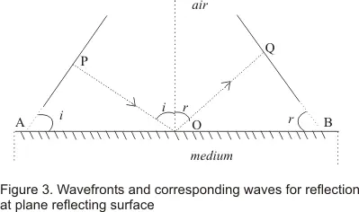
- POQ is the ray normal to both incident and reflected wave fronts
- The angle of incidence i and angle of reflection r are the angles made by incidence and reflected rat respectively with the normal and these are also the angles between the wave fronts and the surface as shown in the figure 3
- The time taken by the ray POQ to travel from incident wave front to then reflected one is
Total time from P to Q= t=PO/v1 + OQ/v1
where v1 is the velocity of the wave. From figure (3)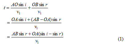
- There can be different rays normal to incident wave front and they can strike plane reflecting surface at different point O and hence they have different values of OA
- Since tome travel by each ray from incident wave front to reflected wave front must be same so, right side of equation (1) must be independent of OA.This conditions happens only if
(sini-sin r)=0
or i=r
Thus law of reflection states that angle of incidence i and angle of reflection are always equal
- Consider the figure given below which shows a plane surface AB separating medium 1 from medium 2
- v1 be the speed of light in medium 1 and v2 the speed of light in medium 2
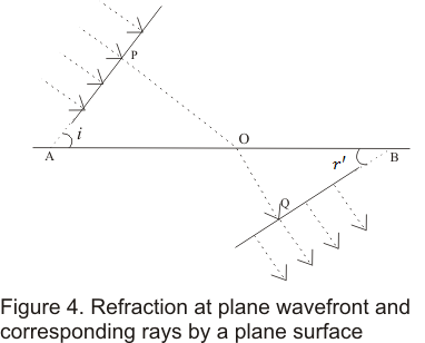
- Incident and refracted wave front makes angles i and r' with surface AB where r' is called angle of refraction
- Time taken by ray POQ to travel between incident and refracted wave fronts would be
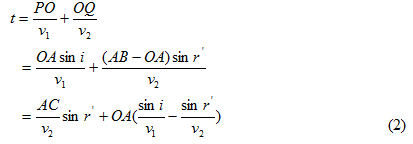
- Now distance OA would be different for different rays .So time t should be independent of any ray we might consider
- This can be achieved only if coefficient of OA in equation (2) becomes equal to zero or
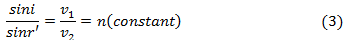
- Equation (3) is nothing but Snell’s law of refraction where n is called the reflective index of second medium with respect to the first medium.
- The ratio of phase velocity of light c in vacuum to its value v1 in a medium is called the refractive index n1 ( or μ1) of the medium .Thus

- When light travels from medium 1 to medium 2,what we measure is the refractive index of medium 2 relative to medium 1 denoted by n12 ( or μ12).Thus
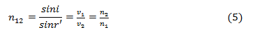
where n1 is refractive index of medium 1 with respect to vacuum and n2 is refractive index of medium 2 w.r.t. vacuum - When light travels from one medium to another the frequency ν=1/T remains same i.e. ν1=ν2
- Since the velocities of light v1 and v2 are different is different medium ,the wavelength λ1 and λ2 are also different i.e.,
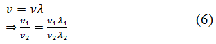
the wavelength of light in the medium is directly proportional to phase velocity and hence inversely proportional to the refractive index
- When two or more sets of waves travel through a medium and cross one another the effects produced by one are totally independent of the
- At any instant the resultant displacement of a particle in the medium depends on the phase difference between the waves and is the algebraic sum of the displacement it would have at the same instant due to each separate set. This is known as the principle of superposition of waves and forms the basis of whole theory of interference of waves discovered by Young in 1801
- If at any instant y1,y2,y3,--- are the displacements due to different waves present in the medium then according to superposition principle resultant displacement y at any instant would be equal to the vector sum of the displacements (y1,y2,y3) due to the individual waves i.e.,
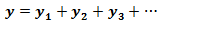
- The resultant displacement of the particles of the medium depends on the amplitude ,phase difference and frequency of the superposing waves
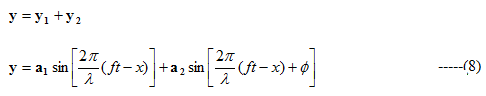
- Consider two waves of same frequency f and wavelength λ travelling through a medium in the same direction and superpose at any instant of time say t
- Equation of these waves at time t is
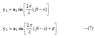
where φ is the phase difference between the waves - According to principle of superposition of waves ,resultant displacement of particles equals
Now from trigonometry identity
Putting it in equation (8) we find
Let us suppose
Putting them in equation (9) we have
where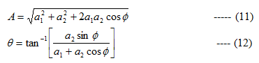
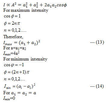
- We know that intensity of waves is proportional to its amplitude i.e.
6) Interference of light waves
- Interference of light wave is the modification in distribution of light energy obtained by superposition of two or more waves
- At some points where crest of the one wave falls on the crest of another ,resultant amplitude is maximum
- At some points where crest of one wave falls on trough of another, the resultant amplitude become minimum and hence intensity of the light is minimum
- At points, where the resultant intensity of light is maximum ,the interference is said to be constructive
- At points where resultant intensity of light is minimum ,interference is said to be destructive
- Coherent sources are those sources of light which emit continuous light waves of same wavelength ,same frequently and are in same phase or have a constant phase difference
- For observing interference phenomenon ,coherence of waves is a must
- For light waves emitted by two sources of light to remain coherent ,the initial phase difference between waves should remain constant in time. If the phase difference changes continuously or randomly with time then the sources are incoherent
- Two independent sources of light are not coherent and hence cannot produce interference because light beam is emitted by millions of atoms radiating independently so that phase difference between waves from such fluctuates randomly many times per second
- Two coherent sources can be obtained either by the source and obtaining its virtual image or by obtaining two virtual images of the same source. This is because any change in phase in real source will cause a simultaneous and equal change it its image
- Generally coherence in interference is obtained by two methods
i) Division of wave front where wave front is divided into two parts by reflection ,refraction or diffraction and those two parts reunite at a small angle to produce interference such as in case of Young Double slit experiment ,Fresnel bi-prism .
ii) Division of amplitude whose amplitude of a section of wave front is divided into two parts and reunited later to produce interference such as in case of interference due to thin films - Laser light is almost monochromatic with light spreading and two independent laser sources can produce observable interference pattern
- Two sources should continuously emit waves of same wavelength or frequency
- The amplitudes of the two interfering waves should be equal or approximately equal in order to reduce general illumination
- The sources of light must be coherent sources
- Two sources should be very narrow as a broad source is equivalent to large number of narrow sources lying side by side which causes loss of interference pattern resulting general illumination
- Two sources emitting set of interfering beams must be placed very close to each other so that wavelength interact at very small angles
9)Young Double slit experiment
- Young in 1801 demonstrated interference phenomenon through double slit experiment
- In his experiment ,he divided a single wave front into two and these two slit wave fronts acts as if they emerged from two sources having fixed relationship
- when these two waves were allowed to interfere ,they produce a sustained interference pattern
- In his original experiment he illuminates a pin hole S using a light source and light diverging from pinhole which contains two sets of pinholes S1 and S2 equidistant from S and very close to one another as shown below in the figure
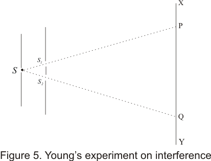
- Two two sets of spherical waves coming out of the pin holes S1 and S2 were coherent and interfered with each other to form a symmetrical pattern of varying intensity on screen XY
- This interference pattern disappear when any one of the pinholes S1 or S2 is closed
- Young used the superposition principle to explain the interference pattern and by measuring the distance between the fringes he managed to calculate the wavelength of light.
- In young's double slit experiment ,light wave produce interference pattern of alternate bright and dark fringes or interference band
- To find the position of fringes, their spacing and intensity at any point P on screen XY .Consider the figure given below
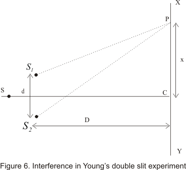
- Here S1 or S2 two pin holes of YDS interference experiment and position of maxima and minima can be determined on line XOY parallel to Y-axis and lying on the plane parallel to S,S1 or S2
- Consider a point P on XY plane such that CP = x.The nature of interference between two waves reaching point P depends on the path difference S2P-S1P
- from figure (6)
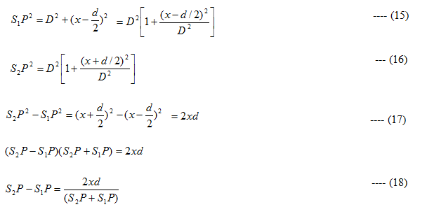
for x, d<<< D , S1P+S2P =2D
with negligible error included , path difference would be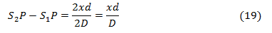
And corresponding phase difference between wave is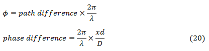
- If the path difference (S2P-S1P) is even multiple of λ/2,the point P is bright
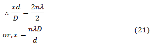
- Equation (21) gives the condition for bright fringes or constructive interference
- If the path difference is an odd multiple of λ/2,the Point P is dark. So,
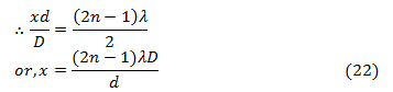
- Equation (22) gives the condition for dark fringes or destructive interference
- From equations (21) and (22) ,we can get position of alternate bright and dark fringes respectively
- Distance between two consecutive bright fringes is given by
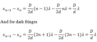
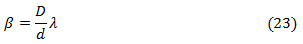
- Thus the distance between two successive dark and bright fringes is same. This distance is known as fringe width and is denoted by β. Thus
11) Displacement of fringes
- when a film of thickness t and refractive index μ is introduced in the path of one of the source of light ,then fringe shift occur as optical path difference changes
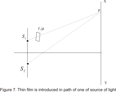
- Time required by light to reach from S1 to point P

where v=c/μ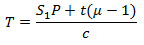
- Hence equivalent path that is covered by light in air is S1P+t(μ-1)
- Optical path difference at P
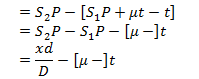
Therefore nth fringe shift is given by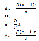
where λ is the wavelength of the wave
No comments:
Post a Comment