
Electric Current ,Resistance and Resistivity
(1) Introduction
- In our previous few chapters of electrostatics,we have discussed various terms and characterstics related to charge at rest
- Now in this chapter we will study about the moving charges,phenomenom related to them and various effects related to charge in motion
- Consider two metallic conducting balls charged at different potential are hanged using a non conducting insulating wires .Since air is an insulator ,no charge transfer takes place
- Now if we join both the metallic wire using a conducting metallic wire then charge will flow from metallic ball at higher potential to the one at lower potential.
- This flow of charge will stop when the two balls would be at the same potentials.
- If somehow we could maintian the potential between the metallic balls,we will get constant flow of the charge in metallic wire,connecting the two conducting balls
- This flow of charge in metallic wire due to the potential dicference between two conducters used is called electric current about which we would be dicussing in this chapter.
(2)Electric current and Current density
Electric Current
- We already had a brief idea about the electric current which wed defined as the state of motion of the electric charge .Now we are going to study about the electric current in details
- Quantitatively electric current is defined as the time rate of flow of the net charge of the area of crosssection of the conducter i.e
Electric current = Total charge flowing / time taken - if q is the amount of charge flowing through the conducter in t sec,The current through the conducter is given by
I=q/t (1) - SI unit of the current is Ampere(A) named so in the honour of french scientist Andee marie Ampere(1775-1836).Now,
1 Ampere= 1 Coulumb/ 1 sec=1 Cs-1 - Thus current through any conducter is said to be 1 ampere,if 1 C of charge is flowing through the conducter in 1 sec
- Small amount of currents are accordingly expressed in milliamperes (1mA=10-3 A) or in micro ampere (1 mA=10-6 A)
- Direction of electric current is in the direction of the flow of positive charged carriers and this current is known as conventional current.
- Direction of the flow of electron in conductor gives the direction of electronic current. Direction of conventional current is opposite to that of electronic current
- Electric current is a scalar quantity .Although electric current represent the direction of the flow of positive charged carrier in the conductor,still current is treated as scalar quantity as current in wires in a circuit does not follows the laws of vector addition
- The current density at a point in the conductor is defined as the current per unit cross-section area.Thus if the charge is flowing per unit time uniformaly over the area of crosss-section A of the conductor,then current density J at any point on that area is defined as
J=I/A -(2) - It is the characterstic property of point inside the conductor nor of the conductor as a whole
- Direction of current density is same as the direction of conventional current
- Note that current density is a vector quantity unlike electric current
- Unit of current density is Ampere/meter2 (Am-2)
(3) Drift Velocity
- Metallic conductors have large numbers of elctrons free to move about.These elctrons which are free to move are called conduction electrons
- Thus valence electrons of atom becomes the conduction electrons of the metals
- At room temperature,these conduction electrons moves randomly inside the conductor more or less like a gas molecule
- During motion,these conduction electrons collide with ions(remaining positive charged atom after the valence electrons move away) again and again and there direction of motion changes after each and every collision.
- As a results of these collisions atoms moves in a zig-zag path
- Since in a conductor there are large number of elctrons moving randomly inside the conductor.Hence they have not net motion in any particular direction.Since the number of electrons crossing an imaginary area ΔA from left to right inside the conductor very nearly equals the number of electron crossing the same area element from right to left in a given interval of time leaving flow of electric current through that area nearly equals to zero
- Now when we applied some P.D using a battery across the two ends of the conductor,then an electric field sets up inside the conductor
- As a result of this electric field setup inside the conductor,conduction electron expeirence a force in direction opposite to electric field and this force accelerates the motions of the electrons
- As a result of this accelerated motion electrons drifts slowly along the length of the conductor towards the end at higher potential
- Due to this acceleration velocity of electron's increases only for short interval of time as each acclerated electrons suffers frequent collision with positive ions and looses their Kinectic energy
- After each collision electrons starts fresh in random direction ,again get accelerated and loose their gained Kinetic energy in another collision
- This extra velocity gained by the electrons is lost in subsequent collison and the processes continued till the electron reach positive end of the conductor
- Under the effect of electric field inside the conductor ,free electrons have random thermal velocities due to the room tmeperature and small velocities with which they drift towards the positive end of the conductor.
- if τ is the average time between two successive collisions and E is the strength of applied electric field then force on electron due to applied electric field is
F=eE
Where e is the amount of charge on electron - if m is the mass of electron ,then acceleration produced is given by
a=eE/m - Since electron is acclerated for an average time interval τ,additional velocity acquired by the electron is
vd=aτ
or vd=(eE/m)τ (3)
This small velocity imposed on the random motion of electrons in a conductor on the application of electric field is known as drift velocity - This drift velocity is defined as the velocity with which free electrons gets drifted towards the positive end of the conductor under the influence of externally applied electric field
(4) Relation between drift velocity and electric current
- Consider a conducting wire of lenghth L and having uniform cross-section area A in which electric field is present
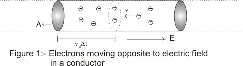
- Consider in the wire that there are n free electrons per unit volume moving with the drift velocity vd
- In the time interval Δt each electron advances by a distance vdΔt and volume of this portion is AvdΔt and no of free electron in this portion is nAvdΔt and all these electrons crosses the area A in time Δt
- Hence charge crossing the area in time Δt is
ΔQ=neAvdΔt
or
I=ΔQ/Δt =neAvd (4)
This is the relation between the electric current and drift velocity - If the moving charge carriers are positive rather than negative then electric field force on charge carriers would be in a direction of electric fields direction and drift velocity would be in left to right direction opposite to what shown in fig-1
- In terms of drift velocity current density is given as
j=I/A=nevd (5)
(5) Ohm's Law and Resistance
- Ohm's law is the relation between the potential difference applied to the ends of the conductor and current flowing through the conductor.This law was expressed by George Simon Ohm in 1826
- Statement of Ohm's Law
'if the physical state of the conductor (Temperature and mechanical strain etc) remains unchanged ,then current flowing through a conductor is always ditectly proportional to the potential difference across the two ends of the conductor
Mathematically
V α I
or
V=IR (6)
Where constant of proportionallity R is called the electric resistance or simply resistance of the conductor - Value of resistance depends upon the nature ,dimension and physically dimensions of the conductor
- Ohm's Law can be deducted using drift velocity relation as given in equation -3 .Thus from the equation
vd=(eE/m)τ
but Now E=V/l
Therfore
vd=(eV/ml)τ
Also I=neAvd
Substituting the value of vd in I relation
I=(ne2Aτ/ml) V (7)
or V/I=(ml/ne2Aτ)=R a constant for a given conductor
Thus
V=IR
Mathematical expression of Ohm's Law
From Ohm's Law
V=IR or R=V/I (8)
Thus electric resitance is the ratio of potential difference across the two ends of conductor and amount of current flowing through the conductor - electric resistance of a conductor is the obstraction offered by the conductor to the flow of the current through it.
- SI unit of resistance is ohm (Ω) where
1 Ohm=1 volt/1 Ampere
or 1Ω=1VA-1 - Dimension of resistance is [ML2T-3A-2]
(6) Resistivity and conductivity
- In terms of drift velocity ,electric current flowing through a conducting wire of length L and uniform area of cross-section A
is
I=dQ/dt =neAvd=(ne2Aτ/ml) V
The above can be rearranged to give the ohm's law i.e,
V=IR
where R=(ml/ne2Aτ) Now R=ρl/A (9)
Where ρ is called the specific resistance or resistivity of the conductor
And ρ=m/ne2τ (10) - From equation (9) ,we can see that resistance of the wire is proportional to its length and inversly proportional to its cross-sectional area.
- Thus resistance of a long and thin wire will greater then the resistance of short and thick wire of the same material
- Now from equation (9)
R=ρl/A (11)
And from ohm law R=V/I
Therefore
ρ=(V/I)(A/L)
=(V/L) / (I/A)
=E/J (12)
Where E=V/L is the electric field at any point inside the wire and J=I/A is current density at any point in the wire. Unit of resistivity is ohm-meter. - Thus from equation (12) ,electric resistivity can also be defined as the ratio of electric field intensity at any point in the conductor and the current density at that point.
- The greater the resistivity of the material ,greater would be the field needed to establish a given current densisty
- Perfect conductor have zero resistivities and for perfect insulators resistivity would be infinite
- Metals and alloys have lowest resistivities and insulators have high resistivities and exceeds those of metals by a factor of 1022
- The reciprocal of resistivity is called conductivity and is represented by σ
- Unit of conductivity is ohm-1meter-1(Ω-1m-1) and
σ is defined as
σ=1/ρ
Since ρ=E/J
or σ=J/E
or J=σE (13a) - The above relation can also be written in vector form as both J and E are vector quatities where vector Jbeing directed towards E
J=σE (13b)
(7) variation of resistivity with temperature
- Resistance and hence resistivity of conductor depends on mubers of factors
- One of the most important factors is dependence of resistance of metals on temperature
- Resistivity of the metallic conductor increases with increase on temperature
- when we increase the temperature of the metallic conductor,its constituent atoms vibrate with greater amplitudes then usual.This results
to the more frequent collison between ions and electrons - As a result average time between the two successive collision decreases resulting the decrease in drift velocity
- Thus increase collison with the increase in tempearture results in increase resistivity
- For small temperature variations ,resistivity of the most of the metals varies according to the following relations
ρ(T)=ρ(T0)[1 + α(T-T0)] (14)
Where ρ(T) and ρ(T0) are the resistivies of the material at temperature T and T0 respectively and α is the constant for given materail and is known as coefficient of resistivity. - Since resistance of a given conductors depends on the length and crosssectional area of the conductor through the relation
R=ρl/A
Hence temperature variation of the resistance can be given as
R=R(T0)[1 + α(T-T0)] (15) - Resistivity of alloys also increase with temperature but this increase is much small as compared to metals
- Resistivies of the non-metals decreases with increase in temperature .This is because at high temperature more electrons becomes avialable for conduction as they set themselves loose from atoms and hence temperature coefficient of resistivity is negative for non-metals
- A similar behavior occurs in case of semi-conductors .temperature coefficient of resistivity is negative for semi-conductors and its value is often large for a semi-conductor materials
(8) Current Voltage relations
- We know that current through any electrical device such as resistors depends on potential defference between the terminals
- Devices obeying ohm's law follow a linear relationship between current following and potential applied where current is directly proportional to voltage applied .Graphical relation between V and I is shown below in figure
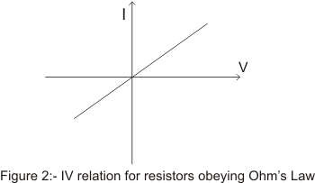
- Graph for a resistor obeying ohm's law is a straight line through the origin having some finite slope
- There are many electrical devices that does not obey the ohm's law and current may depends on voltage in more complicated ways.Such devices are called non-ohmic devices for examples vaccum tubes,semiconductor diodes ,transistors etc
- Consider the case of a semi conductor junction diode which are used to convert alternating current to direct current and are used to perform variety of logic functions is a non=ohmic device
- Graphical voltage relation for a diode is shown below in the figure

- Figure clearly shows a non linear depeence of current on voltage and diode clearly does not follow the ohm's w
- When a device does not follow obey ohm's law,it has non linear voltage -current relation and the quantity V/I is no longer a constant however ratio is still known as resistance which now varies with current
- In such cases we define a quantity dV/dI known as dynamic resistance which expresses the relation between smaal change in current and resulting change in voltage
- Thus for non-ohmic electrical devices resistance is not constant for different values of V and I
(9) Colour code of carbon resistors
- Commercially resistors of different type and values are avilable in the market but in electronic circuits carbon resistors are more frequently used
- In carbon resistors value of resistance is indicated by four coloured bands marked on its surface as shown below in figure
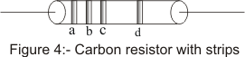
- The first three bands a,b.c determine the value of the resistance and fourth band d gives the tolerance of the resistance
- The colour of the first and second band respectively gives the first and second significant figure of the resistance and third band c gives the power of the ten by which two significant digits are multiplied for obtainng the value of the resistance
- value of different colurs for making bands in carbon resistors are given below in the table
Colur Figure(first and second band) Multiplier(for third band) tolerance Black 0 1 - Brown 1 10 - Red 2 102 - Orange 3 103 - Yellow 4 104 - Green 5 105 - Blue 6 106 - Violet 7 107 - Gray 8 108 - white 9 109 - Gold - 10-1 5% Silver - 10-2 10% no Colour - - 20%
- For example in a given resistor let first strip be brown ,second strip be red and third be orange and fourth be gold then resitance of the resitor would be
12X 103 +/- 5%
(10)Combination of Resistors
- We have earlier studied that sevral capacitors can be connected in series or parallel combination to form a network. In same way sevral resistor may be combined to form a network.
- Just like capacitors resistors can be grouped in series and parallel.
- Equivalent resistance of the combination of any number of resistors is a single resistance which draw same current as the combination of different resistances draw when the same potential difference is applied across it.
(A) Resistors in Series
- Resisors are said to be connected in series combinaton. If same current flows through each resistor when same potential difference is applied across the combination.
- Consider the figure given below
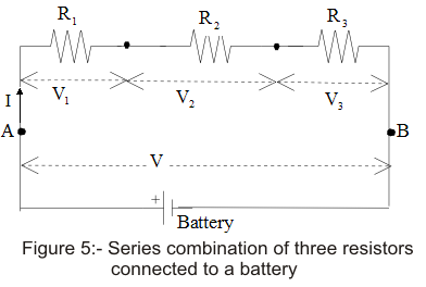
- In figure given above three resistors if resistance R1, R2 and R3 are connected ibn series combination.
- If battery is connected across the series combination so as to mintain potential difference V between points A and B, the current I would pass through each resistor.
- If V1, V2 andV3 is the potential difference across each resistor R1, R2 and R3 respectively, then according to Ohm's Law,
V1=IR1
V2=IR2
V3=IR3
Since in series combination current remains same but potential is divieded so,
V=V1+V2+V3
or, V=I(R1+R2+R3)
If Reqis the resistance equivalent to the series combination of R1, R2 and R3 then ,
V=IReq
where, Req=R1+R2+R3
- Thus when the resistors are connected in series, equivalent resistance of the series combination is equal to the sum of individual resistances.
- Value of esistance of the series combination is always greater then the value of largest individual resisnces.
- For n numbers of resistors connected in series equivalent resistance would be
Req=R1+R2+R3+...........................+Rn
(B) Resistors in parallel
- Resistors are said to be connected in parallel combination if potential difference across each resistors is same.
- Thus , in parallel combination of resistors potential remains the same but current is divided.
- Consider the figure given below
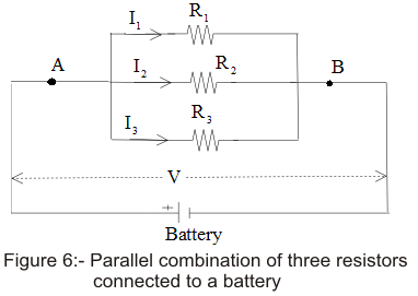
- Battery B is connected across parallel combination of resistors so as to maintain potential difference V across each resistors.Then total current in the circuit would be
I=I1+I2+I3 (16)
- Since potential difference across each resistors is V. Therefore, on applying Ohm's Law
V=I1R1=I2R2=I3R3
or,
From equation (16)
- If R is the equivalent resistance of parallel combination of three resistors heaving resistances R1, R2 and R3 then from Ohm's Law
V=IReq
or,
Comparing equation (16) and (17) we get
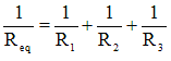
- For resistors connected in parallel combination reciprocal of equivalent resistance is equal to the sum of reciprocal of individual resistances.
- Value of equivalent resistances for capacitors connected in parallel combination is always less then the value of the smallest resistance in circuit.
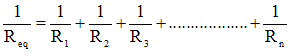
- If there are n number of resistances connected in parallel combination, then quivalent resistance would be reciprocal of
| Colur | Figure(first and second band) | Multiplier(for third band) | tolerance |
| Black | 0 | 1 | - |
| Brown | 1 | 10 | - |
| Red | 2 | 102 | - |
| Orange | 3 | 103 | - |
| Yellow | 4 | 104 | - |
| Green | 5 | 105 | - |
| Blue | 6 | 106 | - |
| Violet | 7 | 107 | - |
| Gray | 8 | 108 | - |
| white | 9 | 109 | - |
| Gold | - | 10-1 | 5% |
| Silver | - | 10-2 | 10% |
| no Colour | - | - | 20% |
12X 103 +/- 5%
(10)Combination of Resistors
- We have earlier studied that sevral capacitors can be connected in series or parallel combination to form a network. In same way sevral resistor may be combined to form a network.
- Just like capacitors resistors can be grouped in series and parallel.
- Equivalent resistance of the combination of any number of resistors is a single resistance which draw same current as the combination of different resistances draw when the same potential difference is applied across it.
(A) Resistors in Series - Resisors are said to be connected in series combinaton. If same current flows through each resistor when same potential difference is applied across the combination.
- Consider the figure given below
- In figure given above three resistors if resistance R1, R2 and R3 are connected ibn series combination.
- If battery is connected across the series combination so as to mintain potential difference V between points A and B, the current I would pass through each resistor.
- If V1, V2 andV3 is the potential difference across each resistor R1, R2 and R3 respectively, then according to Ohm's Law,
V1=IR1
V2=IR2
V3=IR3
Since in series combination current remains same but potential is divieded so,
V=V1+V2+V3
or, V=I(R1+R2+R3)
If Reqis the resistance equivalent to the series combination of R1, R2 and R3 then ,
V=IReq
where, Req=R1+R2+R3 - Thus when the resistors are connected in series, equivalent resistance of the series combination is equal to the sum of individual resistances.
- Value of esistance of the series combination is always greater then the value of largest individual resisnces.
- For n numbers of resistors connected in series equivalent resistance would be
Req=R1+R2+R3+...........................+Rn
(B) Resistors in parallel - Resistors are said to be connected in parallel combination if potential difference across each resistors is same.
- Thus , in parallel combination of resistors potential remains the same but current is divided.
- Consider the figure given below
- Battery B is connected across parallel combination of resistors so as to maintain potential difference V across each resistors.Then total current in the circuit would be
I=I1+I2+I3 (16) - Since potential difference across each resistors is V. Therefore, on applying Ohm's Law
V=I1R1=I2R2=I3R3
or,
From equation (16) - If R is the equivalent resistance of parallel combination of three resistors heaving resistances R1, R2 and R3 then from Ohm's Law
V=IReq
or,
Comparing equation (16) and (17) we get - For resistors connected in parallel combination reciprocal of equivalent resistance is equal to the sum of reciprocal of individual resistances.
- Value of equivalent resistances for capacitors connected in parallel combination is always less then the value of the smallest resistance in circuit.
- If there are n number of resistances connected in parallel combination, then quivalent resistance would be reciprocal of
No comments:
Post a Comment